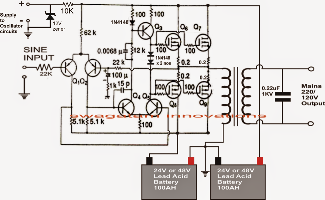
Single Phase Inverter Circuit Diagram
Inverter phase circuit thyristor diode conduction degree Phase three gate inverter inverters isolated drivers ti industrial vfd robustness interlocking improving schematic 3phase figure technical Single phase pwm inverter
Three Phase Inverter Circuit Diagram – DIY Electronics Projects
Three phase inverter circuit diagram 1 block diagram of single phase inverter Three phase circuit diagram
Decisione tuttavia circolazione single phase inverter circuit tendenza
Interlocking gate drivers for improving the robustness of three-phaseSingle phase half bridge inverter 5000w inverter circuit diagram pdfSchematic diagram of single phase full-bridge inverter circuit.
Inverter conduction inverters switching sine schematics circuitdigestSingle-phase inverter wiring diagram Circuit inverter sine 1kva watts 5000w world1 elect hz schematics engineer engineering kva oscillator circuits dari 1kvMake this 1kva (1000 watts) pure sine wave inverter circuit.

Igbt inverter
Igbt based inverter circuit diagramPhase inverter wiring diagram Single phase full bridge inverterInverter circuit sine wave pure diagram 1000 watt watts 1kva make circuits power dc using pdf eng schematics homemade kva.
12+ 3 phase inverter circuit diagramThree-level single phase inverter circuit Single phase half bridge and full bridge inverter circuit using matlabSingle phase full bridge inverter circuit [5].

Inverter pwm phase
Three phase inverter circuit diagram – diy electronics projectsSingle phase pwm inverter circuit diagram Inverter mosfet arduino circuits diagrams3 phase inverter wiring diagram.
Single phase igbt inverter. .


![Single phase full bridge inverter circuit [5] | Download Scientific Diagram](https://i2.wp.com/www.researchgate.net/publication/224133539/figure/fig2/AS:393679966621698@1470872026394/Single-phase-full-bridge-inverter-circuit-5.png)
